|
|
Post by sdboers on Mar 21, 2015 19:23:24 GMT -5
Being the incredibly patient person that I am (NOT!) I picked up a few parts to at least get started on this. You'll see below that I have already encountered my first design challenge.  Figured I'd start with the lid: 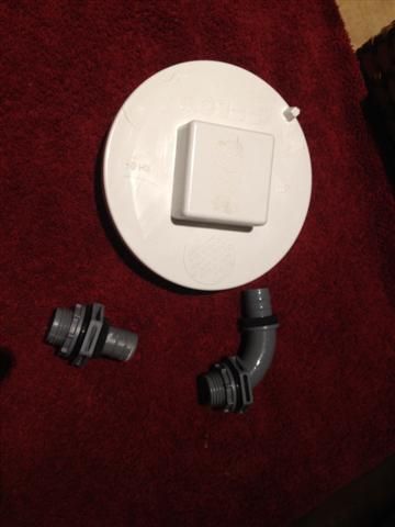 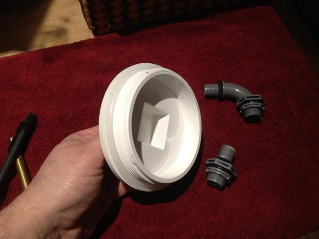 I drilled the whole for the input dead center in the cap and put the bulkhead in. Then I drilled a hole to the side for the output, as close to the edge as I could to allow the ring to screw down. 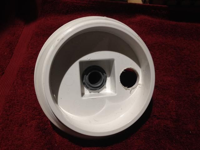 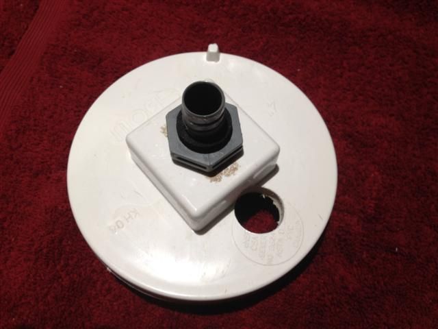 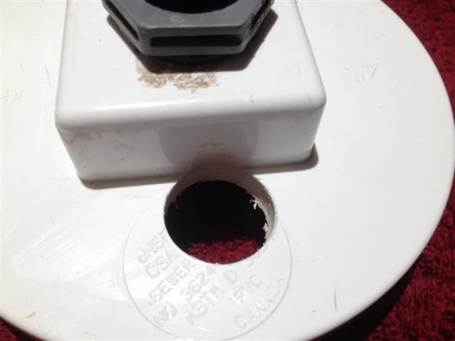 Turns out that leaving enough room on the inside of the cap for the screw ring, means there isn't enough room on the outside of the cap for the fitting - it runs into the raised center part... Sean. |
|
|
|
Post by sdboers on Mar 21, 2015 19:48:56 GMT -5
Solution 1: I could mushroom out the top with an adapter from 4" to 6" and then use a 6" cleanout and plug for the end cap. This would likely give enough room for both the inlet and outlet drilled through the cap.
Solution 2: Cap the main cylinder with a Y (or T) at the top. Maintain the 4" clearout plug at the top with the center infeed drilled. Put another cap on the Y (or T) and drill it for the output.
Solution 3: Rather than a screw in top, I could go back to the design of a clamp down top using draw latches and a machined piece of plastic with an o-ring. Being a flat piece of plastic would mean I would not have to worry about the raised center piece getting in the way.
Solution 4: If I cut the raised part of the plug off, I could then glue a flat piece of PVC over the whole top. Essentially giving me the same option as Solution 3, but screw in instead of clamp down.
Solution 5: Since the o-ring goes on the inside of the lid, and there is enough room - what if I ground down the outside of the bulkhead to fit flush against the raised center part?
Anybody else have any ideas?
Sean.
|
|
|
|
Post by sdboers on Mar 21, 2015 21:39:12 GMT -5
Did I happen to mention how patient I am? lol... So I opted to try solution #5. Worst case scenario - I just wasted a $5 part (the carlon 90 degree liquidtight connector). Here are the results... I think if I replace the oring with some silicone before I screw the ring down, the result should be pretty good. I guess I will find out when I get around to pressure testing it... lol. 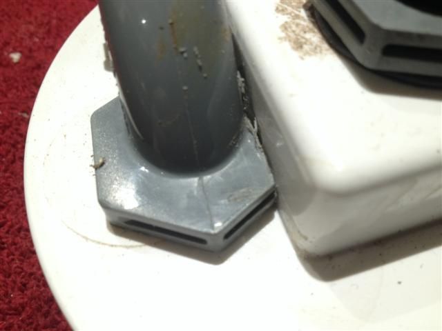 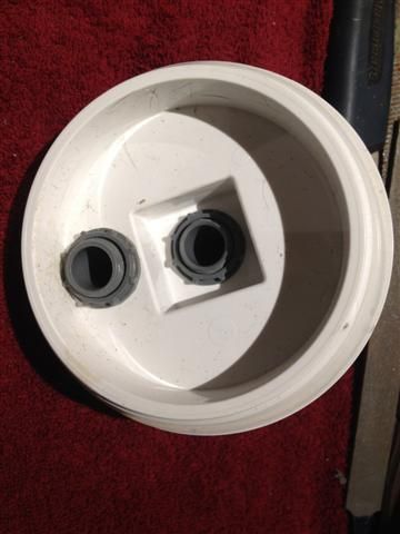 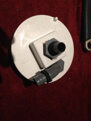 Sean. |
|
|
|
Post by angelminx on Mar 22, 2015 2:17:32 GMT -5
Looks good to me  , I never would have thought of any of that! |
|
|
|
Post by sdboers on Mar 22, 2015 8:06:07 GMT -5
And now for the downspout... If I replace the screw on ring for the center bulkhead with a 1/2" PVC adapter, I can screw it right onto the bulkhead, and then provide a slip on joint for the PVC downspout. 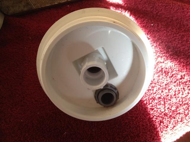 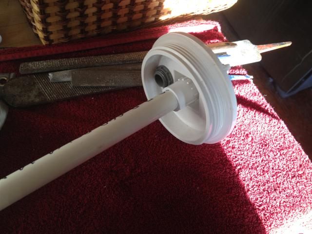 This is about as far as I can go today. Need to go buy more parts. The place where I need to get the clear tube is closed today, so even my impatience can't overcome that. I should note that all of the parts purchased so far came to a total of $19 CAD. The clear tube is another $15 for a 3 foot length. The next question to address is - how tall should I make this thing? If I want to make 2 of them without buying a second piece of clear tube, my maximum height is 18". If I buy one tube per FSB, then my maximum height is 36". I'm not concerned about the cost of the tube at only $15, so I really want to make this the "right" height. Suggestions?Sean. |
|
|
|
Post by Carl on Mar 22, 2015 11:39:02 GMT -5
I think this was a good solution.
If at all possible, I would apply PVC cement any where where there is plastic on plastic, using any plastic shavings in the mix to act as a sort of "plastic mortar". This has worked for me in many customizations of PVC/Plastic parts
Carl
|
|
|
|
Post by devonjohnsgard on Mar 23, 2015 16:31:19 GMT -5
The taller the better for Nitrate removal.
|
|
|
|
Post by sdboers on Mar 23, 2015 17:20:06 GMT -5
Based on Carl's recommendation - I think I'll try 24". I just got offered a used Magdrive 2400 for $50 that needs a new impeller. Seems like a good deal to me and will be way more pump than needed to drive it. Need to scrounge a few more pennies to round this thing out and give it a try. The store for the tube is about 75km from home, so I'll try and get there some time over the next week or so. Sean. |
|
|
|
Post by sdboers on Mar 24, 2015 15:13:58 GMT -5
Ding ding! Time for the next design challenge... So it turns out that 4 inches does not equal 4 inches does not equal 4 inches. I picked up the 4" OD tubing I had mentioned (yeah yeah - mr. impatient...) and it is nowhere close to fitting snug inside the 4" PVC end caps. Here is a picture of the tube inside the end cap: 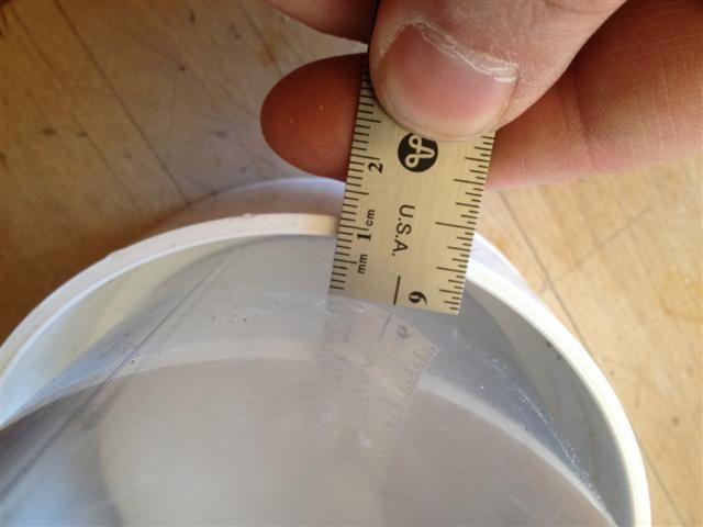 So I wondered if it would fit inside the 4" pipe, that fits inside the end cap. Here you can see that the 4" white PVC pipe will actually slide over the 4" clear tube: 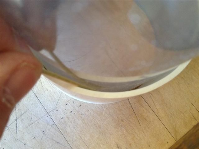 Still doesn't quite work... There is *almost* a toothpick wide gap all the way around: 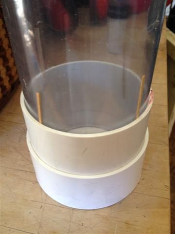 Suggestions? Suggestions?My thought is to use PVC glue to glue the short piece of actual PVC pipe into the end cap to make the overall ID smaller. Then - I'm thinking a gap filling epoxy to glue the clear 4" tube inside the modified end cap. Good idea? Bad idea? Sean. |
|
|
|
Post by sdboers on Mar 24, 2015 15:36:14 GMT -5
Measurements:
PVC end cap ID: 4 1/4"
PVC pipe OD: 4 1/4"
PVC pipe ID: 4"
Clear tube OD: 3 15/16"
So we have a 1/32" gap all the way around.
Sean.
|
|
|
|
Post by Carl on Mar 25, 2015 11:54:53 GMT -5
Measurements: PVC end cap ID: 4 1/4" PVC pipe OD: 4 1/4" PVC pipe ID: 4" Clear tube OD: 3 15/16" So we have a 1/32" gap all the way around. Sean. The epoxy may work assuming adhesion to plastics by roughing up the PVC surface area first. My though would be PVC cement followed by a few windings of Teflon Tape, followed by PVC cements and again Teflon Tape and cement until it fits. This method makes for a chemical bond, unlike the mechanical bond you would get with Epoxy Carl |
|
|
|
Post by sdboers on Mar 25, 2015 12:03:18 GMT -5
Teflon tape?? I never would have thought of that.
I'm assuming the reasoning is that the teflon tape would melt much like the pvc would, and the materials would combine to form a full bond? Am I reading into this correctly?
Sean.
|
|
|
|
Post by sdboers on Mar 25, 2015 18:45:14 GMT -5
Carl, I did a test piece according to your suggestion - several layers of teflon tape and pvc cement. Pics below. I'll give it overnight to cure and see if it hardens up enough. Should there be any give to it by the time it fully cures?? 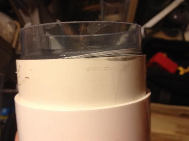 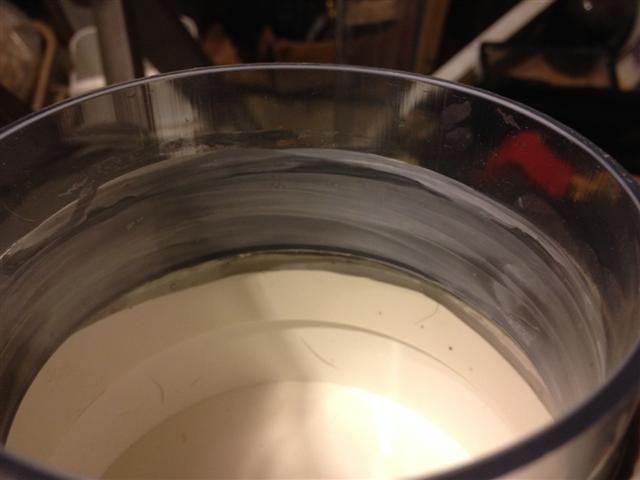 Sean. |
|
|
|
Post by Carl on Mar 25, 2015 18:52:07 GMT -5
Teflon tape?? I never would have thought of that. I'm assuming the reasoning is that the teflon tape would melt much like the pvc would, and the materials would combine to form a full bond? Am I reading into this correctly? Sean. Yes it melts just like the PVC would. I have made many a permanent fix of all sorts of aquarium & pond equipment with this method (as well as fitting irregular parts together in my own DIY projects) This should be safe for water within the hour Carl |
|
|
|
Post by Carl on Mar 26, 2015 11:51:17 GMT -5
You need to use a ratio of PVC to Teflon Tape that melts the tape into the PVC
One other idea I have used with making fittings that are not snug become snug, is the use of PVC shavings mixed into a thick slurry of PVC cement.
This is only good for filling very narrow gaps.
Carl
|
|
|
|
Post by sdboers on Mar 26, 2015 17:32:08 GMT -5
Carl Wile E Coyote - super genius... So leaving that test joint overnight hardened it up quite nicely. I sorta kinda almost maybe have every confidence in that bond. lol... Seriously - I think that will do the trick. On to the next stage, the next thought, and the next question! You'll recall that I'm running the infeed down through the center of the top with a rigid pipe, where it will spew water out at the bottom. It's connected at the top with a slip joint. My issue is - if I remove the top, the pipe will come with it - slip joint or not, and it will be difficult, if not impossible, to get it back down into the sand. My thought is to glue the pipe into another slip joint at the bottom that then glues onto the base (like the picture below) after drilling out the holes (depicted by the blue dots). This way the pipe would remain affixed to the base and the holes would diffuse the water out horizontally. The cap will still have a fairly tight fitting slip joint on top so it can be attached and removed, yet still direct the water downwards. 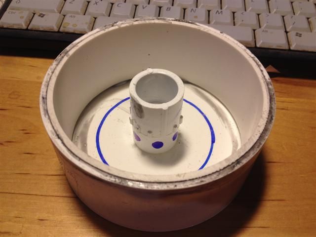 I think that design should work, but as always - I'm open to opinions. Sean. |
|
|
|
Post by sdboers on Mar 27, 2015 9:06:12 GMT -5
|
|
|
|
Post by Carl on Mar 27, 2015 11:38:58 GMT -5
Thanks for the picture, this makes my day, especially since it has not been a good week otherwise! Carl |
|
|
|
Post by sdboers on Mar 27, 2015 11:57:08 GMT -5
If I put a smile on your face - then I have accomplished my goal. Without knowing the specifics - I hope next week is better for you than this week. My wife is traveling this weekend, so that leaves me extra time to putter with aquarium stuff. Muahaha... With any luck, I will be posting a video this weekend of this thing in action. More of a sink based trial than anything, but at least we should get to see if the basic design is sound, if the joints are water tight, and if the sand properly fluidizes or not. But first things first... 2200 pounds of dog food to unload into the shed. Good for another month! Sean. |
|
|
|
Post by sdboers on Mar 27, 2015 19:00:09 GMT -5
Time for the next installment... So - following the advice of Carl - I went with the teflon tape and pvc cement wrap to fill the minor gap between the pvc end caps and the clear tube (1/32"). I found that 5 layers was just about perfect to make it fit nice and snug. I started by drilling holes all the way around the 1/2" to 1/2" slip connector that will be used as a diffuser. I then glued it to the bottom end cap: 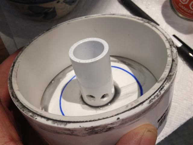 After 5 wraps of teflon tape and pvc cement, the end cap goes onto the clear tube: 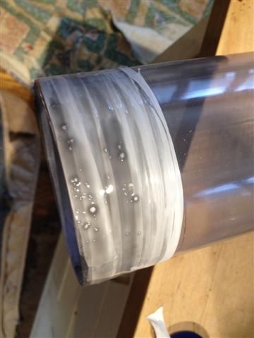 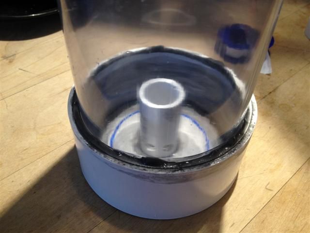 Same thing for the other end, and we're almost there... 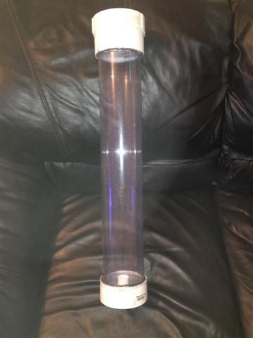 Sean. |
|


 Or please consider a donation, even just $5 helps. If even 25% of users of this information donated just $5, it would be more income than one year of sales (currently less than 1/1000 of a % donate)


 , I never would have thought of any of that!